
Key Takeaways
- CNC machining supports repeatable production by following verified digital tool paths.
- Thoughtful design, stock selection, tooling, and inspection can reduce scrap before it occurs.
- Accuracy, precision, and repeatability are related, but each affects part quality differently.
- Stable fixtures and practical cutting conditions help prevent vibration, tool damage, and rework.
- Five-axis machining can reduce setups for complex parts, although it is not necessary for every job.
Metal components must do more than look correct on the first run. They need to fit, function, and remain consistent across the entire order. Reviewing how a CNC machine shop approaches programming, workholding, and inspection can help project teams understand the decisions behind dependable machined parts.
Computer numerical control equipment follows programmed movements rather than relying on hand-guided cutting. That makes production more repeatable, but a machine can also repeat the same mistake quickly if the model, setup, tools, or program have not been properly checked.
Why Consistency Matters in Metal Parts
Consistency matters whenever a component mates with another part, seals a fluid path, supports a load, or needs to be replaced later. Accuracy describes how close a measurement is to the intended value. Precision describes how closely repeated measurements agree. Repeatability is the ability to produce the same result repeatedly under comparable conditions.
A well-controlled CNC process helps keep holes, slots, edges, and surfaces within the required limits from one part to the next. However, the target tolerance must be realistic. Specifying tighter tolerances than a part requires can increase cycle time, inspection effort, and the likelihood that otherwise functional parts are rejected.
How CNC Machining Reduces Waste
Effective CNC machining reduces more than discarded chips. It can also limit wasted machine time, broken tools, repeated inspections, unnecessary finishing passes, coolant consumption, and energy spent while equipment is idle or recutting a failed feature.
CAM software allows tool paths to be reviewed before the stock reaches the machine. Simulation can reveal collisions, poor tool access, or inefficient moves that would otherwise consume time and material. Process optimization also matters. Oak Ridge National Laboratory describes how stable cutting parameters can reduce scrap and improve material removal rates by addressing chatter and tool vibration.
Design and Process Planning
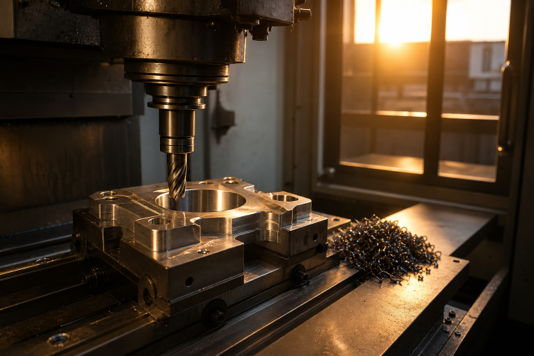
Waste prevention starts during design, not after a part fails inspection. Design for manufacturability, often called DFM, involves reviewing a model with the actual cutting process in mind. A feature may be possible to machine but still require specialized tools, multiple setups, or unusually slow finishing operations.
Questions to Ask Before Machining
- Are tight tolerances necessary for the part’s function?
- Can standard cutters reach internal corners and deep pockets?
- Will thin walls flex or vibrate during cutting?
- Can the part be held securely without damaging critical surfaces?
- Can a common bar, plate, tube, or blank reduce excess material removal?
Choosing Starting Material
The right starting form can reduce both chip volume and machining time. Round bar is often efficient for shafts, plate is well-suited for brackets and flat profiles, and tube may be appropriate for hollow parts. Castings and forgings can be useful near-net blanks for repeat production, while oversized blocks are often practical for prototypes or unusual shapes.
The least expensive raw stock is not always the lowest-cost choice overall. A low-priced block that requires extensive roughing may result in greater tool wear, longer cycle times, and more recyclable scrap than a blank that begins closer to the finished geometry.
Tooling, Fixtures, and Cutting Conditions
Tooling and workholding directly affect dimensional control. If a fixture allows movement, the part can chatter, shift, develop poor surface finish, or miss a critical measurement. Long tool reach can create similar problems because the cutter becomes less rigid as it extends farther from the holder.
Process Factors That Need Attention
- Tool material, coating, and wear condition
- Spindle speed, feed rate, depth of cut, and tool engagement
- Coolant delivery and chip evacuation
- Fixture rigidity and clamping pressure
- The material’s tendency to generate heat, vibration, or built-up edge
Faster is not automatically better. A thin aluminum bracket may need lighter clamping and a careful finishing pass, while a heavy steel component may require a rigid fixture, stronger tools, and a different cutting strategy. The best settings balance speed, control, and tool life.
Quality Control During Production
Inspection should begin with the first completed part rather than waiting until the batch is finished. Teams should confirm the drawing revision, material, setup, and critical dimensions early, then perform in-process checks as tools wear and conditions change. Calipers and micrometers are well-suited to many basic checks, while height gauges, optical systems, and coordinate measuring machines can support more complex inspection needs. A coordinate measuring machine records three-dimensional coordinates, making it useful for verifying locations, profiles, and relationships between features.
Where Five-Axis Machining Fits
Five-axis equipment can position a cutting tool and workpiece in more directions than a basic three-axis setup. For complex geometry, this may improve access to angled surfaces and reduce the number of repositioning steps. Fewer setups can reduce alignment risk, but a simple flat part may still be faster and more economical on a three-axis machine.
The practical question is not whether five-axis machining is better in general. It is a matter of whether the geometry, positional tolerances, number of machined faces, and production volume justify the added capability and programming effort.
Common Mistakes That Increase Scrap
- Using an outdated drawing or program: Apply clear revision control before setup.
- Starting with oversized stock: Compare available forms and near-net blanks before ordering material.
- Ignoring tool wear: Track tool life and inspect finish changes during the run.
- Skipping simulation or first-part checks: Verify the process before committing to full production.
- Using unstable workholding: Review clamping, support points, and cutter access together.
- Mixing metal chips: Separate compatible scrap streams to make recycling more practical.
A Practical Project Checklist
- Define the part’s function and identify its critical features.
- Confirm the material, thickness, and most suitable stock form.
- Apply tight tolerances only where they are functionally needed.
- Review tool access, wall thickness, and workholding requirements.
- Select the simplest machine setup that meets the requirements.
- Plan first-part and in-process inspections.
- Track scrap, cycle time, rework, and tool wear after production begins.
Final Thoughts
CNC machining can help manufacturers make metal parts more consistently while reducing avoidable waste. The strongest results come from combining practical design choices, suitable starting stock, stable fixturing, controlled cutting conditions, and timely inspection. When these factors are planned together, quality and efficiency reinforce each other.

MOBI ROLLER is a tech enthusiast with a background in technology. He writes about the latest trends, tools, and innovations in the tech world, sharing insights based on both knowledge and experience.